Jockey Journal Forum banner

Simple Shovelhead Wiring Diagram Needed

72K views 41 replies 6 participants last post by  Erlomd  
#1 · (Edited by Moderator)
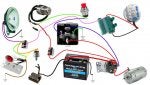
So, I’m in need of a simple wiring diagram for my 1977 shovel project.

I’m running the following:

-a hella single beam headlight
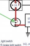
-Handlebar has a starter button, toggle engine kill switch, and brake lever switch
-2 wire barrel ignition key
-Crane Digital ignition
-Regulator
-Starter
-Starter solenoid
-Dyna coil with 2 terminals
-Rear brake light switch
-Tail light

No turning signals, horn, or anything else.

*on a side note, I do have the frame-mounted wiring distribution block in the back of the Dyna coil.

Thanks, guys, for your help
 
#4 ·
it would be in your best interest to up date the charging system to the evo 32 amp as every bike shop has a regulator if you run the roads and your not stuck waiting on the mail for an 11 amp to show up

what you want is very easy to accomplish - draw it out on paper 8 colors should do it and a 20 amp plastic circuit braker but I will look for a diagram
 
  • Helpful
Reactions: JJ Admin
#6 ·
I made a diagram of what mine looks like at the moment...(Its all messed up can't get anything to work right).

so the colored one is how its set up right now which isn't doing me any good...

and a blank one in case anyone has any suggestions.

Thanks again guys.

Image


Image
 
#7 ·
I think John gives good advice and do as he says; I run an Evo charging system on all my Shovels.

That said, 32A for a chopper or stripped-down bike is complete overkill. If you do this, burn the headlightall the time or you'll be cookin' batteries.
 
#10 · (Edited)
yeah, my diagram was completely garbage...nothing worked right. :(

So, I updated it with this one...(hopefully everything is ok?)

let me know if anything is missing or incorrect. thanks guys

Also, silly question but won't the battery drain its charge if the voltage regulator is constantly on the positive terminal of the battery?

Image
 
#11 · (Edited)
Couple of wrong wires again. No reg wire goes to battery with no breaker.
Some diagrams.
https://www.pinterest.com/carvel24/amf-shovelhead-diagrams/
On battery positive terminal, Reg wire, large wire to solenoid battery terminal, and a breaker. On breaker, wire to ignition switch. On ignition switch, lights (lower amp breaker than one on battery breaker optional, and I would switch the running lights), starter button, and ignition [can run threw kill switch on bars]. On starter button wire to Bosch relay terminal 86 and ground 85. From solenoid bat terminal [long stud], wire to 30 on bosch relay. From solenoid start terminal [little terminal] wire to bosch 87. From solenoid starter terminal [short stud], large wire to starter.
 
#12 · (Edited)
Couple of wrong wires again. No reg wire goes to battery with no breaker.
Some diagrams.
https://www.pinterest.com/carvel24/amf-shovelhead-diagrams/
On battery positive terminal, Reg wire, large wire to solenoid battery terminal, and a breaker. On breaker, wire to ignition switch. On ignition switch, lights (lower amp breaker than one on battery breaker optional, and I would switch the running lights), starter button, and ignition [can run threw kill switch on bars]. On starter button wire to Bosch relay terminal 87 and ground 85. From solenoid bat terminal [long stud], wire to 30 on bosch relay. From solenoid start terminal [little terminal] wire to bosch 87. From solenoid starter terminal [short stud], large wire to starter.
Thanks! heres the diagram with what you mentioned...

Image
 
#17 ·
Now lose the red wire between the solenoid bat stud and load side of the breaker, solenoid will need a battery size cable from bat positive to the solenoid bat terminal [long stud].
Also lose the breaker on the reg to bat positive terminal.
Green wire from the start button goes to the load side of the ignition switch, not to ground at terminal 85 on the Bosch. Orange wire also belongs on ignition load side.
 
#19 ·
i wouldnt use a breaker from the regulator before the battery, but between the battery an the main feed to the switch, & why 2 brakers before the lights ?... do it simply & it's easier, in my drawing i didn't show them but you only need one or two on the whole bike really, you are not using as much as a stock bike after all
 
#21 · (Edited)
thats about right I'd say, ........but when you come to wire it, you might find that it will be neater if the + feed from the battery goes direct to the ignition switch with the 30a fuse/breaker in line,
& the heavy + cable going on it's own to the solenoid from the battery.
purely for a less messy routing,
that way you just have one feed to the switch distributing the power direct from there.
if you see what i mean and closer to the factory diagram as well,
see my diagram BELOW,
I have altered it to add the breakers and remover the idiot lights & hi/lo.
without the oil pressure light & switch you should fit an oil guage off of the rear rocker nut in the right side of the motor for visual safety but if you want a minimalist bike don't fit one
 

Attachments

#23 ·
That's great to hear! And I like the cleaner wire routing! Tomorrow I'll sort it all out on the bike. If everything works (I hope) then I'll dedicate the time to Cutting, soldering, organizing and routing all the wires.

I also have the stock frame mounted wire distribution Block in back of the coil so maybe some wires can meet up there for a more tidy look.

Thanks again for all the help!
 
#38 · (Edited)
so that when the relay sends power via the hi-tension cable to the solenoid,
it at the same time (via the 'bridging' wire) 'excites' the solenoid so it engages the clutch throw out arm engaging the bendix to the ring gear,
at the same time it shunts the Hi-tension feed to the starter via the hi-tension shunting contacts within the dual function solenoid,
It performs the2 things at the same time, but seperatly so to speak from the same unit.
if this does not happen the starter will not spin & not turn the motor over,
which is the whole point of the solenoid.....
you are complicating it by wanting to use a small low tension relay instead of the stock harley type relay or the heavy duty small relay from W&W as shown to you in a previous post,...
as you do not seem to want to listen & just do it & keep asking various people the same questions repeatedly after being told how to do it I am out of here,
 
#41 ·
Image

Only thing wrong with this pic is green wire to starter button should go to the white wire coming out of the ignition switch. As is starter button will always be hot. Wire the bike. Pete's in a hurry.;)