Jockey Journal Forum banner
21 - 40 of 363 Posts
Sure Raz,

First single phase (2 hot legs) enters the knife switch box at the bottom of the box. Leg #2 is jumped(split) to power up what will become the third leg. Time-delay fuses are installed so that the breaker doesn't trip during initial start-up.

Image


Then the third leg power is sent down to a start capacitor. It returns up and into the momentary (light switch) switch. It then goes down and "bump starts" the idler motor which is bolted to the side of my mill.

With zero load on the idler motor, it creates a steady third leg (L3) which can now be used by the mill & lathe.

Image


Though still a bit messy, the circuits can be identified on the wall board in this last photo. When running only one machine, the circuits (L1, L2, & l3) are very well ballanced and the "created 3rd leg" is at 92% - 96% amperage which is just about perfect. When running both(mill & lathe) machines simultaneously, amperage on L3 drops to 88% so I just plug in to the dayton run cap (blue star in photo) and this brings it back up to 95%.

Image


Total expenses were $80 this includes the idler motor(ebay), fuses, romex, capacitors, and light switch. The knife switch came with the mill when I got it, so that was a freebie.
I have heard of this done before but nobody explained it as well as you have.Nice job ,esp when multible applications are needed.I have printed this and put in my notes for future reference.....Thanks
 
F.St.M.

I applaud your make do creativity, but your electrical installation is a disaster.

Get an enclosure for those live parts before someone gets zapped. Those lugs are an electrocution hazzard, especially with either motor under load.
 
a stand for holding stuff, the arms adjust vert. and horizontaly

Image


neck fixture for an as yet unfinished frame jig

Image


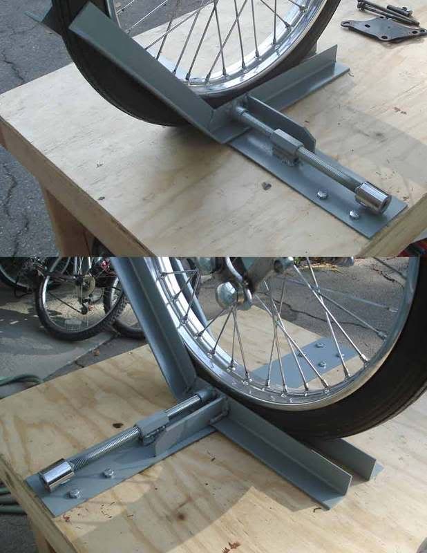
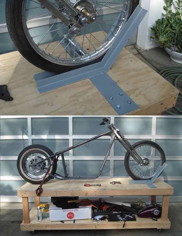
probably too dark to see but a combo wheel chock / tie down

Image


over center bike lift

Image


some mods to a HF tubing notcher
Image


kids in shop class using a T-dolly
Image


this table has been one of the most useful things ever, has casters and makes moving things around the shop super easy, a '26 roadster is sitting on it now and I just push it around the shop
Image


homemade Les Paul :)
Image
 
The thing was actually pretty decent for a HF tool right out of the box. The only things I did were mount it to a good heavy base (I built a wood one first but the 1/4" steel plate is much better). The biggest problem I found is that the pipe clamp didnt quite line up with quill, hole would be drilled off center. All I had to do was put some shim stock between the pipe clamp (the black piece) and the frame (the gray piece) to line it up. I think the biggest secret to making it work is good hole saws.
 
I use this tool to pressure test my intake manifold. Super easy to find even the smallest leaks.

Image


Image

  1. Remove the carb
  2. Bolt this onto the end of the intake using the rubber inner tube "gasket" to seal it up.
  3. Put my air compressor hose on the nipple and adjust the regulator to 10psi.
  4. Spray all around the intake o-rings with water with a little bit of dish soap.
If you have a leak, you'll get lots of bubbles. Much more reliable way to find intake leaks then spraying around the intake with WD40 or carb cleaner.

-Craig
 
I've been in the mood to make some items for the garage. I'll get pics of my metal brakes, english wheel, and parts washer and post them up. In the mean time....bump.
 
F.St.M.

I applaud your make do creativity, but your electrical installation is a disaster.

Get an enclosure for those live parts before someone gets zapped. Those lugs are an electrocution hazzard, especially with either motor under load.
I usualy try to avoid licking the live lugs on the wall when I'm machining something, so enclosing them is not a concern.
 
21 - 40 of 363 Posts